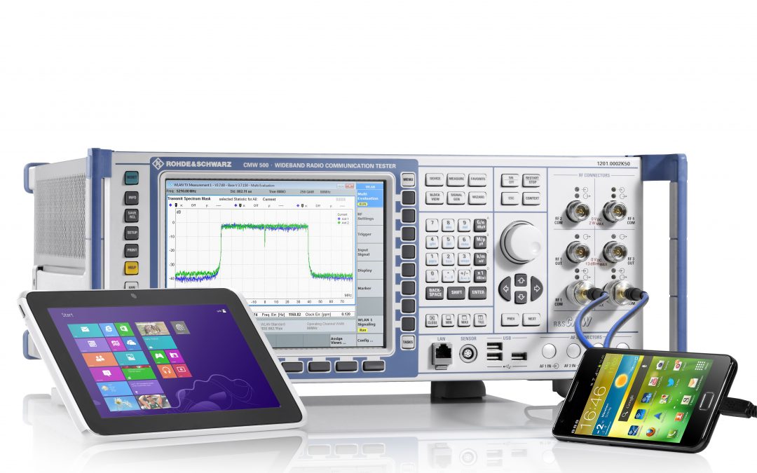
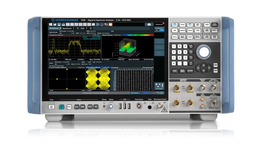
The R&S CMW500 wideband radio communication tester from Rohde & Schwarz is suitable for diverse WLAN tests in production and development. This includes comprehensive measurements of MIMO transmissions up to IEEE 802.11ax as well as coexistence tests with radio standards such as Bluetooth®, GPS, LTE, WCDMA, GSM and Zigbee. Source: Rohde & Schwarz
Multiple input multiple output (MIMO) is a multi-antenna technology that can help to significantly accelerate WLAN transmissions and optimize the signal quality. However, WLAN radio modules require additional test procedures in production and development covering the specified MIMO techniques.
In MIMO transmissions, signals are sent via multiple transmit antennas to multiple receive antennas. Reflections along the path to the receiver produce the multipath propagation that MIMO requires. The IEEE standardization committee has specified various MIMO techniques for the 802.11n/ac/ax standards. They can be used to boost the data rate or the signal quality. For each transmission, the WLAN router and WLAN station negotiate which of the techniques to use. Key parameters include the prevailing transmission conditions, the requirements for the data rate and signal quality, and the device configuration.
2×2 MIMO for small devices
The WLAN modules in small devices such as smartphones or compact tablets are generally configured to handle a maximum of 2×2 MIMO. More than that is not possible due to the required minimum spacing between antennas of one half wavelength. In the 2.4 GHz frequency band, this is equal to one half of 12.5 cm. In addition, multi-antenna systems need more power for their RF amplifiers, which can increase the energy consumption as well as the temperature. The following examples illustrating MIMO techniques as well as test and measurement equipment are based on MIMO-capable devices with a maximum of two transmit and two receive antennas.
Higher data rates with spatial multiplexing
The MIMO technique of spatial multiplexing significantly increases the data rate compared to single-antenna systems, for example. The outgoing data stream is divided among several spatial streams that are simultaneously transmitted to the receiver on the same frequency by means of different transmit antennas.
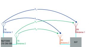
Fig. 1: In spatial multiplexing, each receive antenna receives a sum signal consisting of all of the transmitted signals. The prevailing channel conditions are represented in a transmission matrix H with elements hnm.
Source: Rohde & Schwarz
Decoding in 2×2 MIMO means the receiver has to solve a system of equations with two equations and two unknowns. This is only possible if the equations are linearly independent. In physical terms, this necessitates multipath propagation on separate, uncorrelated transmission paths.
In order to decode the transmission matrix H, the matrix elements must be known. The receiver autonomously determines these elements using open-loop channel estimation based on known bit sequences in the transmitted data packets. Under ideal conditions, 2×2 MIMO with spatial multiplexing can achieve double the data rate of single-antenna systems.
TX diversity for higher signal-to-noise ratio
In addition, various methods are specified that can improve the signal quality based on TX diversity. These methods involve using more transmit antennas than receive antennas in order to boost the signal-to-noise ratio. Transmission is thus less susceptible to interference, which also extends the range. The data rate can also be increased if the improved signal quality allows the use of higher-order modulation (16QAM/64QAM/256QAM/1024QAM). The signal-to-noise ratio can be increased in various ways.
Timing offset for stronger signals
In the method known as cyclic shift diversity (CSD) or cyclic delay diversity (CDD), a signal is transmitted several times with a defined timing offset. Variable signal delays arise due to multipath propagation over transmission paths of different lengths. A transmitted signal reaches the receiver with different timing offsets. If an AP now transmits the signal via multiple antennas with a defined timing offset, the various multipath signals are superimposed at the receive antenna, which ideally helps to boost the receive signal. This virtual echo in the transmitter increases the receiver’s frequency selectivity.
Space time block coding for more robust behavior
In space time block coding (STBC), the outgoing data stream is transmitted redundantly via two transmit antennas (Fig. 2), but is only received via a single antenna.
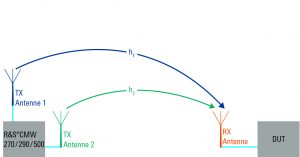
Fig. 2: In space time block coding, the modified outgoing data stream is transmitted via multiple antennas and received via a single antenna.
Source: Rohde & Schwarz
Compared to the original data stream, the redundant signal is permuted in time and complexly conjugated. This system is known as Alamouti’s code in honor of its developer, Siavash Alamouti, who created it for communications with two antennas.
As with spatial multiplexing, the two data streams can only be decoded here if there are separate, independent transmission channels from transmitter to receiver. Under ideal conditions, using two transmit antennas increases the signal-to-noise ratio by 3 dB, thereby doubling it.
Targeted beamforming
The TX diversity technique known as beamforming works without multipath propagation. The transmit signal is sent with a timing offset or phase offset via multiple antennas or antenna arrays. Depending on the geometrical arrangement and spacing of the individual transmit antennas, the signal is amplified, attenuated or even canceled out in various directions. Data streams can be targeted at specific WLAN stations and suppressed for other stations.
Multi-user MIMO
Multi-user MIMO (MU-MIMO) is a typical application of beamforming. If only one access point (AP) and one WLAN station are using a MIMO technique, this is known as single-user MIMO (SU-MIMO). In MU-MIMO, however, the AP sends different MIMO streams to a number of WLAN stations which can have one or more receive antennas. Devices that support IEEE 802.11ax are configured accordingly, while small devices can only process two data streams simultaneously. In order for the receiving device to receive its intended data stream with high field strength, the APs use beamforming in MU-MIMO to target the signals at the desired receiver (Fig. 3).
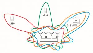
Fig. 3: Multi-user MIMO system with spatial multiplexing based on beamforming.
Source: Rohde & Schwarz
The above techniques can be combined in a variety of ways. For example, the signal-to-noise ratio of a spatial diversity data stream can be improved with space time block coding. This results in a 2×2 MIMO stream being transmitted with 4×2 MIMO (four transmit antennas and two receive antennas).
Testing MIMO functionality
Every MIMO-capable WLAN module requires testing of the relevant functions all the way from development through series production. However, the test requirements that apply during the development process are significantly different from those in production.
Requirements for production tests
During production tests, transmitters and receivers must undergo calibration and inspection on a time-optimized basis. As the device under test (DUT), the WLAN module is remote-controlled via an electrical connection and operated in an artificial non-signaling mode. For such production tests, the test instrument only needs to be equipped with a signal generator and an analyzer. The test duration is primarily dependent on the tester’s measurement speed as well as the number of points and the test depth. If manufacturers try to minimize the test duration by defining as few measurement points as possible and only performing very superficial testing at these points, they run the risk that the product will no longer achieve the specified minimum quality. As a result, they must always keep the applicable risks in mind when attempting to streamline the test plan.
(cont.)
Realistic tests in development
During development, WLAN MIMO devices should be tested under realistic conditions. This is the only way to predict how they will actually behave during subsequent operation and optimize their characteristics. Time and time again, it has been shown that WLAN radio modules can behave differently during real-world operation compared to artificial non-signaling mode. The test duration mostly plays a subordinate role during the development phase since the main goal is to optimize the module. Depending on the scenario, the test instrument ideally emulates either an access point (AP) or a WLAN station (STA), allowing the DUT to connect like under normal operating conditions. Known as signaling mode, this allows developers to examine various test criteria in different situations. Measurements in signaling mode have the major advantage that they do not require wire-connected and device-specific remote control of the DUT. However, the required test time is increased.
RF tests for receivers
During development of WLAN modules, the RF characteristics of the receiver and transmitter are very important. There are various ways to measure these characteristics: By simultaneously measuring the packet error rate (PER) via all of the MIMO receive antennas, for example, the receiver sensitivity can be investigated in MIMO signaling operation. After successfully decoding a transmitted data packet, the DUT sends an acknowledgment (Ack) to the test instrument from which it received the packet. The PER is then calculated based on the number of received acknowledgments vs. the total number of transmitted data packets. A developer can determine the extent to which the implemented space time block coding algorithm optimizes the MIMO transmissions for the module under development, for example.
RF transmitter tests
In terms of the RF characteristics of the built-in transmitters, the main focus is on EMC measurements and signal integrity. The transmitters must reliably fulfill the applicable legal requirements such as the maximum allowed transmit power. They should avoid interference to other radio transmissions and emit signals with high spectral purity to ensure dependable radio communications. Ultimately, the level of user satisfaction is also dependent on these factors.
During tests involving 2×2 MIMO operation, the transmit power, spectrum and modulation accuracy are simultaneously measured and analyzed under real conditions for both transmitters. Typical tests are, for example, the transmit spectrum mask measurement in order to detect unwanted signals, as well as the error vector measurement (EVM) to evaluate a transmitter’s modulation accuracy (Figs. 4 and 5).
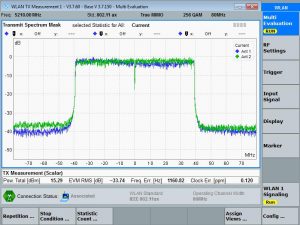
Fig. 4: The transmit spectrum mask measurement determines the power distribution for both MIMO transmitters within a frequency range with respect to the total transmit power. Unwanted signals outside the permissible frequency range are easy to identify.
Source: Rohde & Schwarz
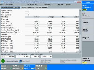
Fig. 5: The error vector measurement (EVM) makes it possible to evaluate a transmitter’s modulation accuracy. Here, the measurement is performed simultaneously for both MIMO transmitter paths. Depending on the modulation and coding, different limits are defined in the standard.
Source: Rohde & Schwarz
Coexistence tests
It is a major challenge for developers of modern communications devices to integrate multiple radio modules, along with a number of antennas, into the very confined space of a single device. For example, smartphones have antennas for Bluetooth®, WLAN, GPS, LTE, WCDMA and GSM. Since many of these standards operate independently, simultaneously and to some extent also in overlapping or adjacent frequency ranges, it is critical to minimize the mutual interference that arises. For example, WLAN reception should not suffer in case of simultaneous transmission via LTE or Bluetooth. Likewise, during transmission via the WLAN antenna, interference to the LTE or Bluetooth receive antennas should be minimized. Implementing coexistence test scenarios of this kind in a reproducible manner requires a signaling-enabled test instrument that allows realistic operation under laboratory conditions.
Since MIMO is primarily intended to boost data throughput, it makes sense to use a test instrument that is capable of determining the data throughput in the transmit and receive directions for the transmission control protocol (TCP) and the user datagram protocol (UDP). Sometimes the desired data throughput is not achieved, even though RF measurements on the transmitters and receivers do not reveal any particular problems. In such cases, error analysis focusing on the transmission protocols can help to clarify the source of the problem.
Further requirements for test equipment
Above and beyond these tests, a WLAN test solution should be used to analyze the current drain under different operating conditions in order to help developers to optimize the battery life. Since the different measurements and investigations can be very time-consuming overall, it makes sense to use automated test sequences for convenient configuration of the whole process. This also provides a foundation for an objective evaluation and leads to comparable measurement results.
Summary
High user satisfaction ‒ in combination with the worldwide success of WLAN ‒ is dependent in part on the numerous tests performed in development and production. As the WLAN standard has undergone further development, the challenges facing instruments used for WLAN testing have also grown. Initial test solutions are already available for comprehensive measurements covering MIMO transmissions up to the WLAN standard IEEE 802.11ax, including coexistence tests.
Author: Thomas A. Kneidel is a product manager for WLAN and WiMAX test and measurement based on the R&S CMW radio communication test platform at Rohde & Schwarz in Munich.
Related Articles
Anritsu, Sony Semiconductor validate industry first Non-Terrestrial Network (NTN) NB-IoT testcase
First NTN NB-IoT Protocol Conformance Tests for have been validated on the 5G NR Mobile Test Device Platform Anritsu Corporation has announced that the first NTN NB-IoT Protocol Conformance Tests for has been validated on the 5G NR Mobile Device Test Platform ME7834NR...

Ellisys Introduces Support for CCC Digital Key Technology
Protocol Updates Aid in Test, Validation, and Debug for Automotive and Consumer Electronics Developers and Test Labs Ellisys, a leading worldwide provider of Bluetooth®, Universal Serial Bus (USB), Ultra-Wideband, and Wi-Fi® protocol test and analysis solutions has...
Rohde & Schwarz 170 GHz power sensors ease use and traceability in the D-band
Rohde & Schwarz is launching the new R&S NRP170TWG(N) thermal power sensor for precise power level measurements in the D-band. The new R&S NRP170TWG(N) sensors from Rohde & Schwarz are used in general R&D for 6G mobile communications, novel sub-THz...
Stay Up to Date With The Latest News & Updates
Our Sponsors
Incisor.TV partners with leading organisations in the technology sector.
Follow Us
And stay up to date with our news! We are active across the key social media platforms – please do follow us!
0 Comments